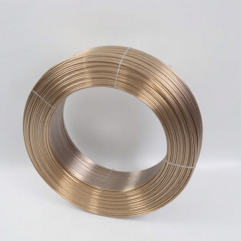
What makes ER4943 suitable for heavy duty automotive and aerospace joints

As lightweight design continues to shape automotive and aerospace engineering, material choices that balance weldability with in service performance get renewed attention. Aluminum Welding Wire ER4943 appears frequently in specification conversations because it combines reliable deposition behavior with post weld characteristics that suit structural joints and components exposed to demanding conditions.
Why ER4943 is considered for high strength applications rests on a few practical traits. Fabricators value a filler that deposits metal with good mechanical balance so welds resist cracking under dynamic loads yet remain workable in routine shop environments. In many production and repair scenarios ER4943 produces a weld bead that is well behaved during cooling which helps control residual stress and reduce the need for extensive straightening or additional mechanical work.
Modern manufacturing pressures add context to filler selection. Trends such as faster electrification cycles, growth in lightweight structures, and tighter service expectations mean teams cannot tolerate frequent rework or extended qualification windows. When a filler like ER4943 shows predictable feed behavior and a repeatable bead profile, production planners can move from pilot to run more quickly. That predictability matters as supply chains fluctuate and projects race to meet tighter delivery windows.
Applications where ER4943 is often chosen include structural brackets and gussets on vehicle frames, secondary airframe assemblies, and components where corrosion resistance and weld strength must coexist. In electric vehicles, battery support structures and mounting points benefit from fillers that accept protective finishes and tolerate cyclic loads. In aerospace, secondary structures and interior frames that require controlled distortion and reliable failure modes are frequent uses. In coastal and marine adjacent projects, the ability to accept coatings without creating crevice prone transitions is a practical advantage.
Turning alloy potential into consistent weld quality involves preparation and process discipline. Cleanliness is the first step. Aluminum oxide forms quickly and interferes with fusion, so dedicated brushing and clean staging areas reduce porosity and uneven wetting. Fit up is equally important. Tight joints and minimal gaps let welders use lower heat input and shorter runs, reducing distortion and helping the filler deposit metal uniformly.
Heat management and sequencing are central to achieving high strength outcomes. When welding with Aluminum Welding Wire ER4943 keep runs short on thin sections and stagger welds across large panels so heat does not accumulate in one area. Allow controlled cooling between passes and use tack spacing that holds geometry without trapping thermal stress. For multi pass welds document interpass limits and maintain consistent travel speed to produce similar microstructure along the joint.
Feeder setup and wire handling also affect results. Match drive roll grooves to the wire diameter and confirm liner compatibility to avoid feed hesitation. Run a short bench feed in the actual feeder path as a pilot; photograph the bead as a visual acceptance sample and note drive roll settings. These small shop practices reduce the chance of unexpected behavior when a spool enters production and create repeatable starting points for different operators.
Shielding and gas flow support weld cleanliness and fusion. Maintain a calm shielding envelope and consider gas lens accessories for hand work if visibility and arc stability are critical. Shielding that is disturbed by drafts or open environments produces surface roughness and increases the chance of defects that reduce joint strength.
Post weld handling and finishing close the loop on durability. Include the heat affected zone in coating overlaps and avoid leaving narrow untreated crevices near the bead. If parts require anodizing or sealing, perform adhesion checks on a pilot weld to confirm the finish process accepts the deposited metal without extra preparation. Simple finish planning prevents routine touch ups and helps inspection teams focus on critical areas.
Inspection, traceability and documentation are practical enablers. Record spool codes, pilot bead photos, and exact welding parameters so any later field issue ties back to a clear production record. Non destructive spot checks and visual acceptance criteria shorten audit cycles and help maintenance teams prioritize interventions based on documented weld history rather than assumptions.
Training and short audits maintain consistency across shifts. Small differences in torch angle stick out and travel rhythm influence bead geometry and heat input more than marginal alloy differences. Regular brief refresh sessions paired with quick visual audits keep results reproducible and reduce operator related variation.
In sectors where range, efficiency and structural integrity are central, weld filler choice influences both production and lifecycle cost. ER4943 offers a mix of weldability and post weld behavior that helps teams meet load and finish demands without adding complex process steps. When procurement and fabrication align on pilot testing packaging and acceptance criteria, ER4943 becomes a practical element of a predictable production plan.
For specification details, handling notes and application guidance that support pilot testing and shop level acceptance consult the technical resources and product pages available at www.kunliwelding.com which provide practical material information and handling suggestions that fabricators can adapt into their workflows.
- Art
- Causes
- Crafts
- Dance
- Drinks
- Film
- Fitness
- Food
- Jogos
- Gardening
- Health
- Início
- Literature
- Music
- Networking
- Outro
- Party
- Religion
- Shopping
- Sports
- Theater
- Wellness


